| DOI:10.5281/zenodo.18222036 2026-01-12 22:44:06 |
| DOI: 10.5281/zenodo.18222036 |
| physical internet 2026-01-12 17:43:15 |
| Physical Internet A Proposal for a Consent-Based Small-Parcel Delivery Infrastructure Using
Utility-Pole Unit Networks
Author: Satoru
Document type: Concept proposal (illustrated) 
Version: v3 | Date: 2026-01-07 Note: The cover image is an AI-generated concept illustration. It does not represent the exact dimensions,
scale, materials, transparency, or handoff positions of the real system.
|
| physical internet Table of Contents 2026-01-12 17:48:52 |
| Table of Contents 1. Introduction: Infrastructure as the real speed 2. System Overview: Unit Network, Home Units, IMS, and Customs Gate (optional) 3. Physical Design: Pipes, Spherical Packets, Storage and Drop-Off Model
Reference Figure: Electromagnetic Coil and Spherical Packet (Concept Image) 3.1 Packet Send/Receive Terminal (Inner Sphere + Outer Shell Sphere) 3.2 Water Delivery Terminal (Dedicated Outer Shell + Direct Tank Connection) 4. Ledger (Memory) and Map (Topology) 4.0 Token-Based Reward Design and Ledger Control (Core of the Backbone Network) 4.1 Packet Identification and Tracking (Continuous Positioning and Delivery Assurance) 4.2 Congestion/Collision Avoidance via Cooperative Unit AIs (Non-Stop Operation Control) 4.3 Early Development and Simulation of Distributed Unit AI (Reachability Without Central Monitoring) 4.4 Multi-Layer Unit Placement (Layer Key) and 3D Route Expansion 5. Delivery Protocol (Consent Required) 6. Safety and Misuse Countermeasures (Hazard Blocking, Grey Isolation, Terminal Lock) 6.1 Anti-Theft: Monitoring, Detection, Evidence, Response 6.2 Evacuation Control for Abnormal Packets (Autonomous Decisions Inside Units)
7. Congestion Avoidance (Home Slots, Empty-Packet Repositioning, IMS Buffer) 8. Routing (Least-Congestion = Effective Shortest Time) and Tracking 9. Tokenomics and Governance (Investment, Rewards, Usage-Based Voting) 10. Software L1/L2 (Two-Layer Architecture) 11. No Backdoors and Open Core 12. Integrated Operator AI (Monitoring-as-Deterrence Concept) 13. Customs Gate (National Sovereignty Domain) 14. Constraints and Future Work 15. Conclusion
|
| physical internet 1. Introduction (Infrastructure as the real speed) 2026-01-12 19:27:03 |
| 1. Introduction (Infrastructure as the real speed) When people imagine a 'fast vehicle', they may think of a supercar rather than a compact car. But
what is truly fast is not the vehicle - it is the road (infrastructure).
This document proposes a concept for a 'Physical Internet': using existing utility-pole infrastructure as
a scaffold to deliver small parcels (roughly 10 cm class) to households in minutes.
The concept is not limited to any specific country. It can be applied wherever utility-pole networks
exist or expand. The author, Satoru, first organized the concept in Japanese and aims to publish this
English version to attract potential investors and operators.
|
| physical internet 2. System Overview (Unit Network, Home Units, IMS, Customs Gate) 2026-01-12 19:27:38 |
| 2. System Overview (Unit Network, Home Units, IMS, Customs
Gate) The system treats the pipe segment between utility poles as the basic unit and transports
standardized spherical packets electromagnetically. It consists of (i) a utility-pole unit network, (ii)
home units that act like household mailboxes, (iii) an Inspection & Maintenance Station (IMS)
responsible for inspection, cleaning, isolation, collection, and repositioning, and (iv) an optional
Customs Gate Unit (CGU) for cross-border delivery.
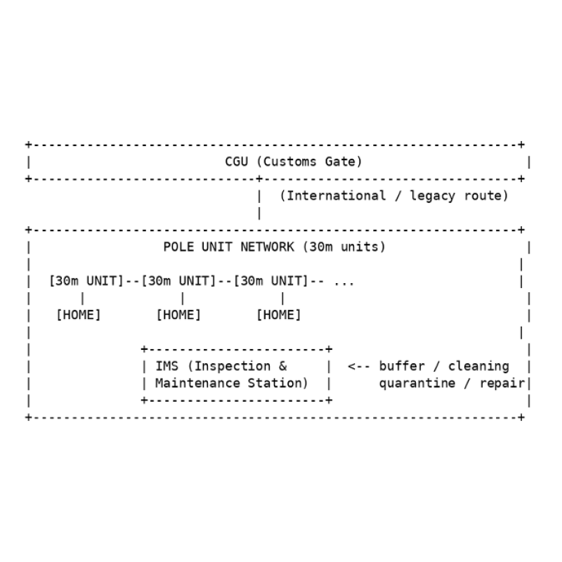
Figure 1. Overall architecture (concept). Home units and IMS connect to the utility-pole unit network; CGU is used only when cross-border routing is required. In this document, a '30 m unit' refers to a structural unit spanning roughly 30 meters between utility
poles. The 30 m value is illustrative and can be adjusted based on local conditions and construction
constraints. By modularizing into units, the structure, contracts, maintenance, and investment units
become explicit, simplifying expansion, replacement, and settlement.
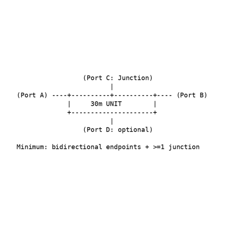
Figure 2. Minimum interface for a 30 m unit (concept): bidirectional endpoints and at least one branch. In principle, the node degree should be at least 3. Reference Figure: Electromagnetic Coil and Spherical Packet
(Concept Image) This image is provided only to support conceptual understanding. It does not represent the exact
dimensions, materials, transparency, or implementation details. (Supporting the explanation of
electromagnetic-coil-based transport.) 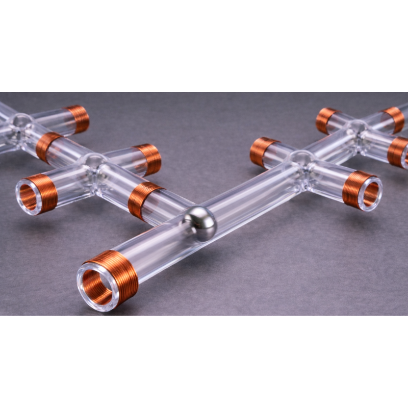 |
| physical internet 3. Physical Design (Pipes, Spherical Packets, Storage and Drop-Off Model) 2026-01-12 19:28:19 |
| 3. Physical Design (Pipes, Spherical Packets, Storage and
Drop-Off Model) The primary physical component is a pipe (approximately 15 cm in diameter) that connects between
utility poles. Inside the pipe, a roughly 10 cm class metal sphere (the spherical packet) travels as the
'packet'. Assuming electromagnetic transport, the pipe houses coils, internal cameras,
communication cables, power cables, edge AI terminals, and sensors.
One structural option is a double-pipe design: an outer pipe of about 15 cm diameter contains a
central inner pipe of about 10 cm diameter (the transport channel). The remaining annular space
(roughly 2.5 cm per side) is used for coils and other equipment. Exact dimensions are left to detailed
engineering; this document presents the basic concept. 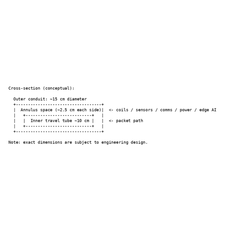
Figure 3. Double-pipe cross-section (ASCII). The inner pipe (about 10 cm) is centered within the outer pipe (about 15 cm); the surrounding space hosts coils, sensors, communications, power, and edge AI. A home unit receives the spherical packet and opens it at a designated position so that the contents
drop into the mailbox area. While this model simplifies mechanisms, it cannot handle fragile items
that cannot tolerate rolling, acceleration/deceleration, or drop impact. As a staged rollout, it is
acceptable to start with receive-only home units for safety and cost reasons. 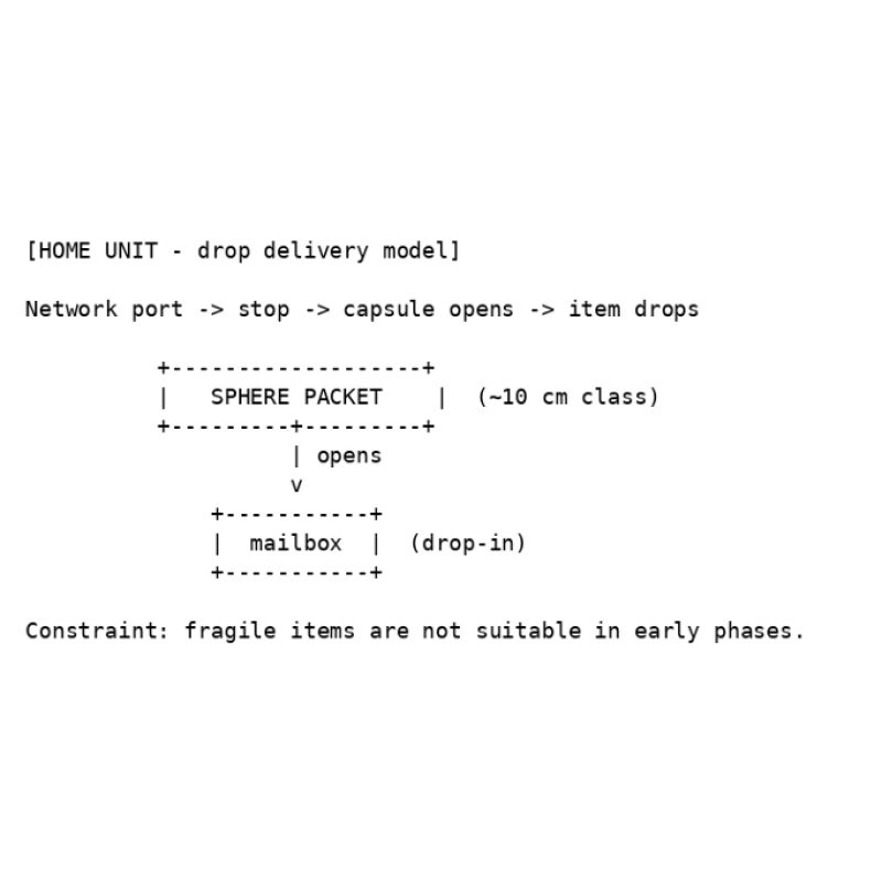
Figure 4. Home-unit drop-off model (ASCII). Fragile items are excluded in the initial specification. As a future extension, the system could also transport liquids. For example, households could
connect a tank unit; in regions where water is scarce, the network may carry only water in leak-proof
packets. Because liquid mode requires quarantine, hygiene, and pressure management, it is
positioned as a later expansion. 3.1 Packet Send/Receive Terminal (Inner Sphere + Outer Shell
Sphere) At each household or facility, the send/receive terminal accepts a user-provided foam spherical
container (the inner sphere). When the user requests delivery via the app, a reusable metal sphere
(the outer shell) arrives from the IMS. Inside the terminal, the outer shell encloses the inner sphere
and the combined packet departs immediately. At the destination, the process is reversed: the outer
shell is separated and recovered; only the inner sphere (the item side) is handed to the recipient.
Outer shells circulate within the system and do not accumulate outside it. • Place the inner sphere (foam container) into the terminal. • Request delivery via the app. • An outer-shell sphere (metal) arrives from IMS, encloses the inner sphere, and departs. • At arrival, the outer shell is recovered and re-injected; only the inner sphere is handed over. 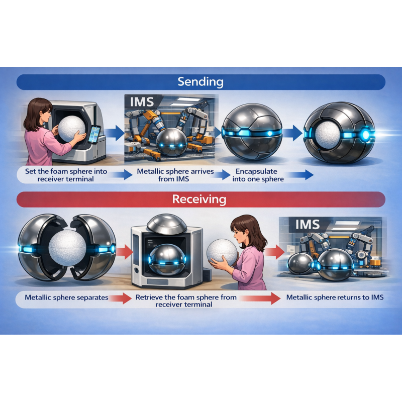
Concept illustration for the terminal and the inner-sphere/outer-shell mechanism (image includes conceptual labels). 3.2 Water Delivery Terminal (Dedicated Outer Shell + Direct Tank
Connection) For water delivery, the system uses dedicated metal spheres (outer shells) reserved for water. The
source-side terminal is connected to a reservoir, and the metal sphere is filled directly inside the
reservoir. The destination terminal is connected directly to a household or facility tank. After arrival,
water is injected from the sphere into the tank and the sphere is recovered and re-injected into the
system. The app continuously monitors tank level and can automatically request replenishment when
it drops below a threshold. • Source terminal: connected to a reservoir; spheres are filled directly in the reservoir. • App: monitors tank level and requests replenishment as needed. • Destination terminal: directly connected to a tank; injects water upon arrival. • Metal spheres: recovered after injection and circulate within the system.
|
| physical internet 4. Ledger (Memory) and Map (Topology) 2026-01-12 19:28:42 |
4. Ledger (Memory) and Map (Topology) 4.0 Token-Based Reward Design and Ledger Control (Core of the Backbone
Network) The backbone of this delivery network is maintained by a crypto-asset token and its distributed
ledger. Installation, operation, maintenance, and transport contributions of each unit are recorded on
the ledger. Usage fees generated by deliveries are distributed as micropayments to the units that
handled pass-through, relays, and maintenance (reward item).
Each unit AI functions as an edge node that contributes to ledger validation and updates - similar in
spirit to mining or staking - and provides network-maintenance functions such as state recording,
audit logs, and local consensus with nearby units.
Beyond settlement, the ledger is used as a control substrate that records unit health, route history,
congestion levels, and inspection results at the Inspection & Maintenance Stations (IMS). Unit AIs
consult the ledger to perform distributed route selection, merge control, and injection control.
Token issuance is capped and released gradually in a way that remains consistent with the initial
deployment plan. After the cap is reached, whether additional issuance is allowed - and changes to
issuance or distribution rules - are decided through on-ledger voting (governance). 4. Ledger (Memory) and Map (Topology) - continued Tokens are not treated merely as speculative assets. The ledger is used to 'remember' system-wide
interactions such as delivery histories, consents, permissions/prohibitions, and adjacency
relationships between units. At first installation, a unit obtains latitude/longitude (e.g., from GPS) and
determines a stable point (GeoAnchor) through an observation period (e.g., three hours). Afterward,
the site maintains its coordinates and records neighboring-unit information on the ledger.
Because unit replacement at the same coordinates is expected, the system separates a SiteID (tied
to the location) from a UnitID (tied to the physical device). During replacement, the ledger explicitly
records expiration of the old UnitID and activation of the new UnitID, and forbids multiple active units
under the same SiteID. 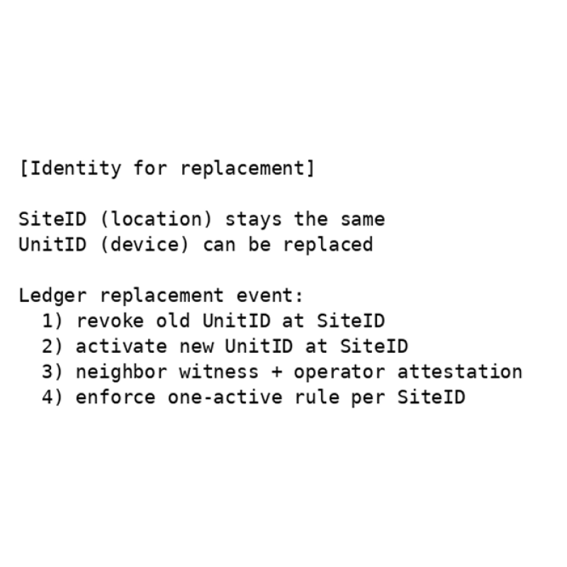
Figure 5. Separation of SiteID and UnitID, and a replacement event (ASCII). The ledger forbids 'multiple active units at the same site'. 4.1 Packet Identification and Tracking (Continuous Positioning and Delivery
Assurance) Each packet carries identifiers such as a barcode and short-range wireless tags (e.g., NFC). Units
automatically read and verify these identifiers using internal cameras and sensors. Using the ledger
history (timestamp, UnitID, latitude/longitude, etc.), the system maintains continuous visibility into the
packet's current position and delivery progress. This enables early detection of delays, route
deviations, mix-ups, and misdeliveries, and supports corrective routing or re-delivery decisions. 4.2 Congestion/Collision Avoidance via Cooperative Unit AIs (Non-Stop Operation
Control) Unit AIs share state with nearby units and automatically adjust speed, spacing, and merge order to
avoid collisions. Under congestion, packets are reassigned to detours based on congestion level; if no
detour capacity exists, the system throttles new shipments through injection control to prevent gridlock.
To avoid looped circulation caused by repeated detours, unit AIs consult ledger history and congestion
levels and cooperatively guide packets toward routes with higher reachability and lower congestion. 4.3 Early Development and Simulation of Distributed Unit AI (Reachability Without
Central Monitoring) Because this delivery method relies on ledger reference and inter-unit cooperation rather than central
monitoring, it should be validated in simulation before building physical devices. Unit AI software is
implemented first, then tested in a simulator with many units and large packet volumes to evaluate
reachability, delivery time, congestion, and loop behavior, iterating improvements. Once standard units
are established, networks can be expanded by connecting units like LEGO blocks. 4.4 Multi-Layer Unit Placement (Layer Key) and 3D Route
Expansion Unit locations are identified by latitude/longitude, and a layer key is assigned at registration time.
Initially, the network operates as a single layer at each coordinate using layer key 0. As an expansion
option when traffic becomes dense, multiple route layers at the same latitude/longitude but different
heights can be added (layer keys 1, 2, ...). Utility-pole networks can expand in the vertical direction;
by detouring to less congested layers, the system can reduce stoppages. A spherical packet design
is advantageous because it can move vertically and traverse three-dimensional branches, enabling
detours that differ from ground transportation and targeting shorter arrival times. • Location ID = latitude/longitude + layer key (initially key 0). • As demand grows, add upper layers at the same coordinates (keys 1, 2, ...). • Unit AIs guide packets to less congested layers based on congestion level. • Spherical packets are well-suited to vertical movement and 3D detours.
|
| physical internet 5. Delivery Protocol (Consent Required) 2026-01-12 19:29:06 |
| 5. Delivery Protocol (Consent Required) A core property of this system is that it does not allow spam-like delivery (one-sided delivery without
consent). A delivery becomes possible only after both the sender and the receiver approve it in
advance. Operations are assumed to be performed via a dedicated smartphone application. 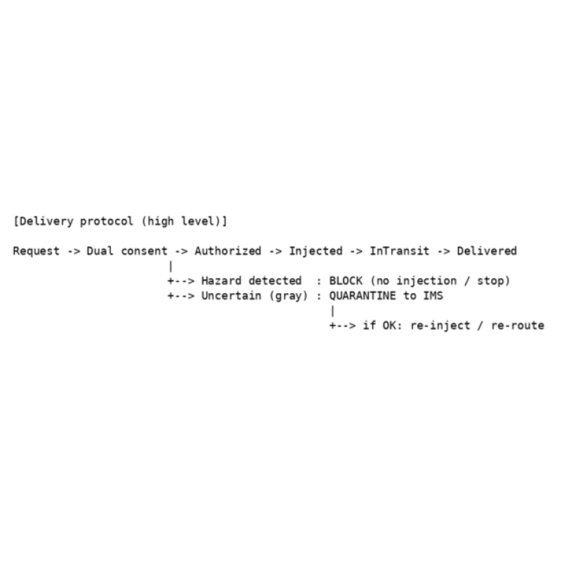
Figure 6. Delivery protocol (ASCII). After mutual consent, a packet is injected; hazards are blocked and grey cases are diverted to IMS. |
| physical internet 6. Safety and Misuse Countermeasures (Hazard Blocking, Grey Isolation, Terminal Lock) 2026-01-12 19:29:31 |
| 6. Safety and Misuse Countermeasures (Hazard Blocking, Grey
Isolation, Terminal Lock) Hazard detection is based on the principle of 'not shippable by default'. If there are hazard indicators,
injection is rejected. Ambiguous cases ('grey') are not delivered to the destination; instead they are
routed to an IMS for inspection, cleaning, and diagnostics. Because spherical packets are reused,
continuous cleaning and inspection stations are essential for hygiene and safety.
For clearly violating users (e.g., repeated attempts to ship dangerous items or repeated policy
violations), the system locks shipping capability from the corresponding terminal via the app to
prevent early infrastructure misuse. 6.1 Anti-Theft (Monitoring, Detection, Evidence, Response) All units include cameras, shock sensors, and damage sensors. Units continuously monitor status and
record video locally; route units include both external and internal cameras. When an anomaly such as
shock or damage is detected, recordings around the event are automatically uploaded to the IMS
server. At the same time, sensor states (type, timestamp, UnitID, etc.) are recorded on the token ledger
as immutable evidence. IMS continuously monitors anomalies and can coordinate police reporting,
on-site checks, recovery/isolation, and repair/replacement. 6.2 Evacuation Control for Abnormal Packets (Autonomous Decisions Inside
Units) If a packet is suspected to be dangerous or abnormal (e.g., hazardous contents, damage, seal
anomalies), the unit immediately reroutes it to a confirmed-safe route. Depending on the situation, the
packet may reverse along the most recent path to return to a safer zone. These evacuation and
route-change actions are decided and executed by the unit's onboard AI based on sensor values,
passability, recent route history, and neighboring-unit state. The time, reason, selected route, and
sensor context are reported to IMS and recorded on the ledger.
|
| physical internet 7. Congestion Avoidance (Home Slots, Empty-Packet Repositioning, IMS Buffer) 2026-01-12 19:29:54 |
| 7. Congestion Avoidance (Home Slots, Empty-Packet
Repositioning, IMS Buffer) Beyond inspection and maintenance, IMS is also central to congestion avoidance. If an empty
spherical packet remains in a home unit, it is automatically forwarded to a nearby IMS after a time
delay, freeing capacity for the next delivery. If a home unit still contains a packet with contents, the
system does not allow the next shipment; the app warns the user to prevent local gridlock caused by
occupied slots. 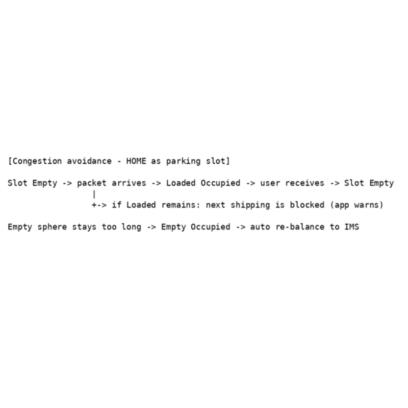
Figure 7. Home-unit slot control (ASCII). Empty spheres are automatically forwarded for repositioning; when a package remains, the next shipment is blocked. |
| physical internet 8. Routing (Least-Congestion = Effective Shortest Time) and Tracking 2026-01-12 19:30:25 |
8. Routing (Least-Congestion = Effective Shortest Time) and
Tracking Delivery routes are computed from the destination unit's coordinates and the ledger-based map,
generating recommended routes that minimize expected delay at the current time. In physical
networks, congestion dominates delay, so the optimization principle is: 'prioritizing routes that are
less likely to clog leads to the shortest effective arrival time'.
Each unit includes an authority AI. When it detects downstream failure or congestion, it may guide a
packet to an alternate route even if it differs from the planned path. Shipment status is recorded to
the ledger as milestone events, and the app displays approximate real-time progress by reading
those events. 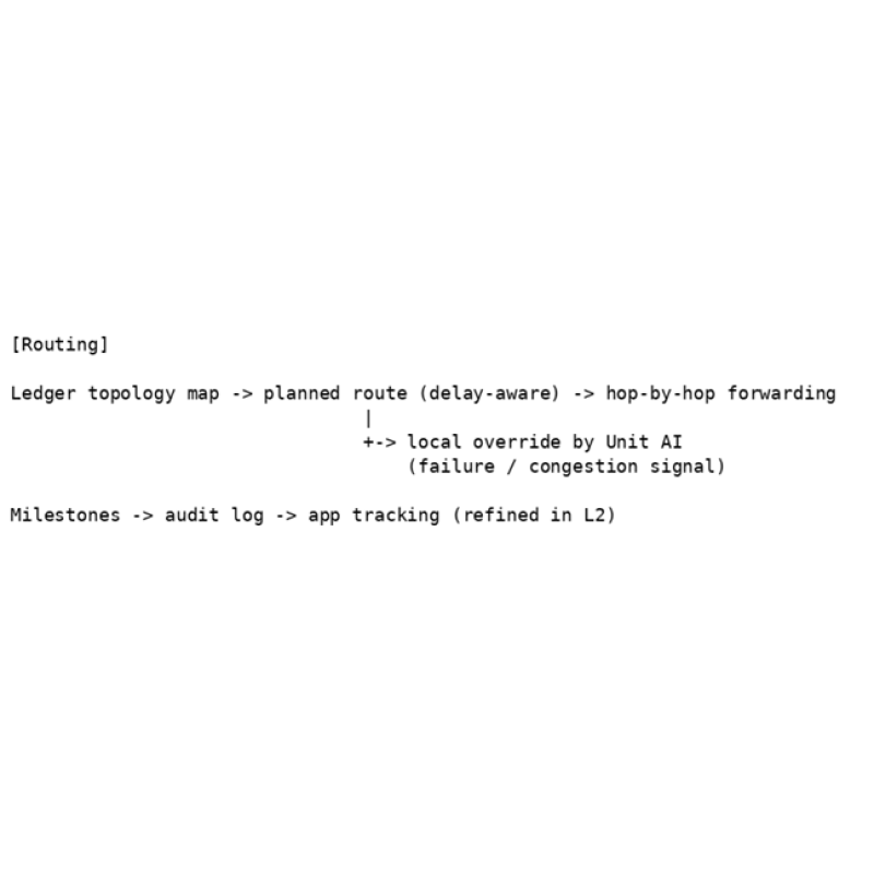
Figure 8. Routing: planned path plus local override by unit AI; milestones for tracking. |
| physical internet 9. Tokenomics and Governance (Investment, Rewards, Usage-Based Voting) 2026-01-12 20:41:12 |
9. Tokenomics and Governance (Investment, Rewards,
Usage-Based Voting) To fund large construction costs, investors purchase utility-pole units similarly to real estate. Every time a
packet passes through a unit, tokens are distributed to the unit owner (each payment is small per
packet but accumulates).
For early momentum, token supply can be fixed initially; after full distribution, additional issuance may
be needed for long-term maintenance. A key feature of this proposal is voting based on usage - not
token balance. In other words, voting power is earned by using the network (sending/receiving),
rather than by holding a large balance.
To avoid fees becoming unrealistically low, maintenance operators publicly disclose electricity and
minimum operating costs and set guardrails such as a fee floor. In rural regions, a consolidated
maintenance company or local governments may install and maintain units. 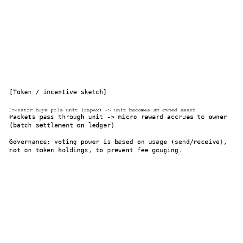
Figure 9. Concept of investment, rewards, and governance (ASCII). Pass-through rewards can be settled in batches; voting is based on usage volume. |
| physical internet 10. Software L1/L2 (Two-Layer Architecture) 2026-01-12 19:31:15 |
10. Software L1/L2 (Two-Layer Architecture) Analogous to crypto L1/L2 (e.g., Ethereum L1 and an L2), the software stack is split into two layers.
The unchanging fundamentals - fixed location, map, consent, safety, and audit - are treated as L1
(immutable). New features and optimizations are implemented as L2 (upgradable). This separation
prevents L2 failures from collapsing the whole network.
L2 may be implemented by large software companies (similar to how Google dominates smartphone
ecosystems). Ideally, users can choose among L2 providers, but network effects may lead to
oligopoly or monopoly. Even in that case, the L1 constitution must prevent deviation. 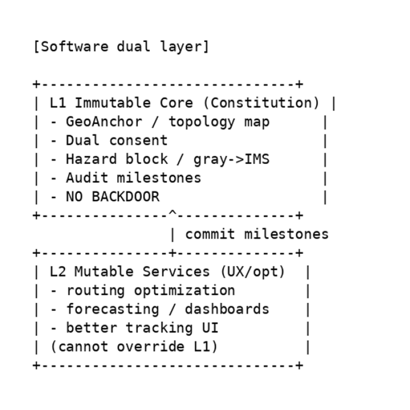 Figure 10. Immutable L1 core and upgradable L2 extensions (ASCII). L2 cannot override L1; on failure, the system falls back to L1 mode. |
| physical internet 11. No Backdoors and Open Core 2026-01-12 19:31:35 |
| 11. No Backdoors and Open Core The system fixes 'no backdoors' as a safety constitution. If a privileged actor could ignore sensors or
consent via a hidden mode, severe misuse (including transporting hazardous items) would become
possible. Therefore, the core (L1) should be open source so that third parties can verify the absence
of backdoors.
At the same time, unit onboarding must be controlled so that malicious units cannot connect
arbitrarily. Joining should be guaranteed through mechanisms verifiable on the ledger, such as
certification by the integrated operator and witnessing by adjacent units
|
| physical internet 12. Integrated Operator AI (Monitoring-as-Deterrence Concept) 2026-01-12 19:32:07 |
| 12. Integrated Operator AI (Monitoring-as-Deterrence Concept) In practice, a consolidated operator company will likely run the network, but human operators may be
influenced by incentives and desires. This proposal introduces the concept of an 'integrated operator
AI'. The idea is to embed the assumption that 'unit AIs are watching the whole system' as a deterrent
against deviation (backdoorization), without fixing the detailed deliberation algorithms today.
Because the evolution of AI is uncertain, the concrete content of monitoring and deliberation is left to
the future. However, the reference basis must remain consistent with the public audit logs defined in
L1.
|
| physical internet 13. Customs Gate (National Sovereignty Domain) 2026-01-12 19:32:30 |
| 13. Customs Gate (National Sovereignty Domain) Whether cross-border routing is needed depends on region and era; ships and air routes will not
disappear. Therefore, customs functions should not be distributed across many IMS sites. Instead,
they should be installed as a small number of 'Customs Gate Units (CGU)', similar to airport customs.
Installation, operating rules, and interconnection conditions are decisions within national sovereignty;
the integrated operator participates only through negotiation.
|
| physical internet 14. Constraints and Future Work 2026-01-12 19:33:06 |
| 14. Constraints and Future Work This document is a conceptual design; implementation requires substantial engineering and
institutional work. Open issues include: the drop-off model excludes fragile items; optimization of
home-unit sensors and cameras; optimal placement of IMS sites; standardization of power,
communications, and maintenance; and social acceptance (regulation, insurance, and liability
boundaries).
Tokenomics questions include: designing an initial capped supply and a post-cap issuance policy;
resistance to abuse in usage-based voting; and transparent reporting methods for minimum
maintenance costs. Staged expansion outlook (from household convenience to backbone) In an initial stage, the key benefit is enabling immediate shipments to and from manufacturers,
warehouses, and individuals while staying at home. Due to the drop-off model and other constraints,
items may be limited to small, non-fragile goods.
Once this convenience is experienced, the network could expand beyond utility poles into a larger
backbone network, potentially using linear-motor technology to handle fragile goods - and eventually
even human transport. If people could travel as 'packets', the travel experience itself could become an
attraction. In an era that may include epidemics, single- or two-person pods that go door-to-door
without unnecessary transfers could reduce contact and friction.
For seniors, such a system could preserve mobility even after a driver's license expires. Optimizing
logistics may also reduce traffic accidents and create broader social benefits.
For that future, the author hopes the project can start small - with ordinary electromagnetic coils and
metal spheres - and expand step by step.
|
| physical internet 15. Conclusion 2026-01-12 19:33:28 |
| 15. Conclusion Speed resides not in vehicles, but in roads. Delivery speed likewise resides in the design and
operation of delivery infrastructure (a physical network). This document proposed a small-parcel
delivery system using a utility-pole unit network as a 'Physical Internet' built on a safety constitution:
consent required, hazard blocking, congestion avoidance, transparent economic design, and no
backdoors
|
| Previous article |
physical internet
 physical internet