2026-01-12 19:28:42
4. Ledger (Memory) and Map (Topology) 4.0 Token-Based Reward Design and Ledger Control (Core of the Backbone
Network) The backbone of this delivery network is maintained by a crypto-asset token and its distributed
ledger. Installation, operation, maintenance, and transport contributions of each unit are recorded on
the ledger. Usage fees generated by deliveries are distributed as micropayments to the units that
handled pass-through, relays, and maintenance (reward item).
Each unit AI functions as an edge node that contributes to ledger validation and updates - similar in
spirit to mining or staking - and provides network-maintenance functions such as state recording,
audit logs, and local consensus with nearby units.
Beyond settlement, the ledger is used as a control substrate that records unit health, route history,
congestion levels, and inspection results at the Inspection & Maintenance Stations (IMS). Unit AIs
consult the ledger to perform distributed route selection, merge control, and injection control.
Token issuance is capped and released gradually in a way that remains consistent with the initial
deployment plan. After the cap is reached, whether additional issuance is allowed - and changes to
issuance or distribution rules - are decided through on-ledger voting (governance). 4. Ledger (Memory) and Map (Topology) - continued Tokens are not treated merely as speculative assets. The ledger is used to 'remember' system-wide
interactions such as delivery histories, consents, permissions/prohibitions, and adjacency
relationships between units. At first installation, a unit obtains latitude/longitude (e.g., from GPS) and
determines a stable point (GeoAnchor) through an observation period (e.g., three hours). Afterward,
the site maintains its coordinates and records neighboring-unit information on the ledger.
Because unit replacement at the same coordinates is expected, the system separates a SiteID (tied
to the location) from a UnitID (tied to the physical device). During replacement, the ledger explicitly
records expiration of the old UnitID and activation of the new UnitID, and forbids multiple active units
under the same SiteID. 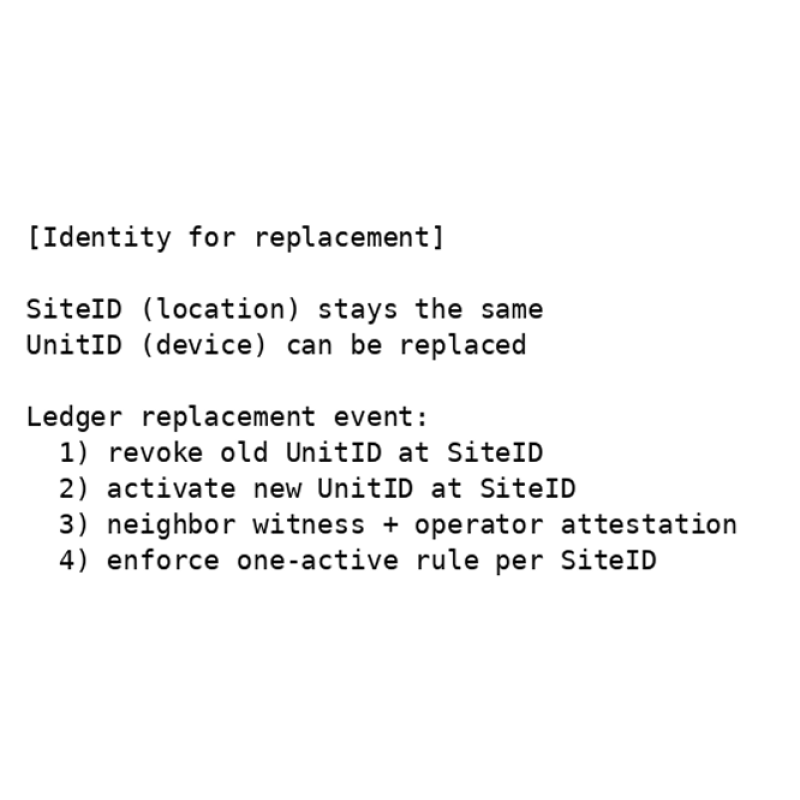
Figure 5. Separation of SiteID and UnitID, and a replacement event (ASCII). The ledger forbids 'multiple active units at the same site'. 4.1 Packet Identification and Tracking (Continuous Positioning and Delivery
Assurance) Each packet carries identifiers such as a barcode and short-range wireless tags (e.g., NFC). Units
automatically read and verify these identifiers using internal cameras and sensors. Using the ledger
history (timestamp, UnitID, latitude/longitude, etc.), the system maintains continuous visibility into the
packet's current position and delivery progress. This enables early detection of delays, route
deviations, mix-ups, and misdeliveries, and supports corrective routing or re-delivery decisions. 4.2 Congestion/Collision Avoidance via Cooperative Unit AIs (Non-Stop Operation
Control) Unit AIs share state with nearby units and automatically adjust speed, spacing, and merge order to
avoid collisions. Under congestion, packets are reassigned to detours based on congestion level; if no
detour capacity exists, the system throttles new shipments through injection control to prevent gridlock.
To avoid looped circulation caused by repeated detours, unit AIs consult ledger history and congestion
levels and cooperatively guide packets toward routes with higher reachability and lower congestion. 4.3 Early Development and Simulation of Distributed Unit AI (Reachability Without
Central Monitoring) Because this delivery method relies on ledger reference and inter-unit cooperation rather than central
monitoring, it should be validated in simulation before building physical devices. Unit AI software is
implemented first, then tested in a simulator with many units and large packet volumes to evaluate
reachability, delivery time, congestion, and loop behavior, iterating improvements. Once standard units
are established, networks can be expanded by connecting units like LEGO blocks. 4.4 Multi-Layer Unit Placement (Layer Key) and 3D Route
Expansion Unit locations are identified by latitude/longitude, and a layer key is assigned at registration time.
Initially, the network operates as a single layer at each coordinate using layer key 0. As an expansion
option when traffic becomes dense, multiple route layers at the same latitude/longitude but different
heights can be added (layer keys 1, 2, ...). Utility-pole networks can expand in the vertical direction;
by detouring to less congested layers, the system can reduce stoppages. A spherical packet design
is advantageous because it can move vertically and traverse three-dimensional branches, enabling
detours that differ from ground transportation and targeting shorter arrival times. • Location ID = latitude/longitude + layer key (initially key 0). • As demand grows, add upper layers at the same coordinates (keys 1, 2, ...). • Unit AIs guide packets to less congested layers based on congestion level. • Spherical packets are well-suited to vertical movement and 3D detours.
|
 physical internet